Hardware Trigger
Setup
To use the hardware trigger, the camera needs to be configured to accept hardware triggers. This can be done both in the viewer or in software.
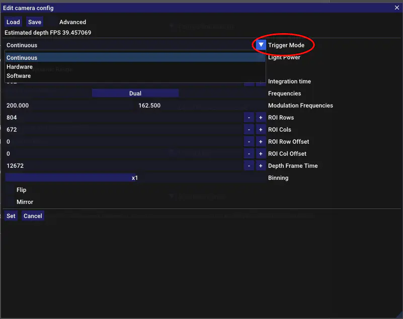
In software it can be done as following.
cam = tof.KeaCamera(serial="2020004")
config = cam.getCameraConfig()
config.setTriggerMode(tof.TriggerMode.HARDWARE)
cam.setCameraConfig(config)
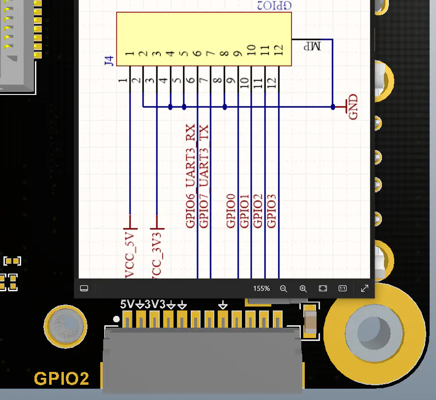
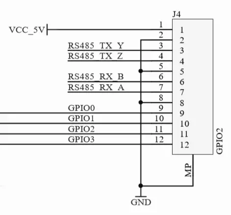
Connector
The GPIO connector is a SM12B-SRSS-TB, located on the bottom of the camera on the right hand side. The mating connector is the SHR-12V-S.
Schematics
GPIO0 is the trigger IN, triggered on the falling edge. It expects a 3.3V voltage and is unprotected so be careful. To keep the light source warm, the camera will run a depth frame internally every 250ms. This depth frame will be discarded. Any trigger that comes in during this time will start a depth frame after the current keep warm one is completed.
GPIO1 is the trigger OUT, it idles low and pulses high on trigger rising edge and stays high for at least 1 us before returning to low. The trigger OUT is always active (i.e. it operates in any trigger mode) and can not be deactivated. The trigger OUT can be used to sync a camera running in continuous mode to a camera that is running in hardware trigger mode.